|
Every so often, a modeller quietly comes along and does something that makes
everyone shake their head in amazement.
You've
seen Howard's work before.....notably his 1/32 cutaway Hurricane in various
print magazines years ago. This is
his latest model....his skinless Wellington.
History
The Vickers Wellington was the main British bomber for the first two years of the
war. The Wellington was designed to meet the requirements of Air
Ministry specification B.9/32. On June 15th 1936 the prototype flew for the
first time. Put
into production in 1936, the first production Wellington flew on December 23,
1937. In 1939 the Wellington started to be delivered R.A.F. Squadrons. The Wellington remained in service
as a land bomber for five and a half years, its initial mission was to attack
the German warships at Wilhelmshafen on the day after war declared, its final raid
was on Treviso in Northern Italy in April 1945. During the last half of the
war, it was replaced by the Avro Lancaster, Handley
Page Halifax and Short Stirling. The Wellington operated, during WW2,
from bases in Great Britain, India, the Middle East, North Africa and Italy.
Due to heavy looses on daylight raids, the
Wellington or "Wimpy" as it is also affectionately called, became a night bomber and from 1940 was also used as a long range
bomber in North Africa. In 1942 the Wellington also became a long range bomber for
the Royal Air Force in India fighting the Japanese. It was well used by Coastal Command as a U-Boat
Hunter. The Wellington remained in service with the Royal Air Force until 1953.
The Vickers Wellington could sustain major damage and still fly, probably due to
its construction of its geodesic structure and practical application of geodesic
lines. Designed by Sir Barnes Wallis Its
utility is proven by the large number built, 11,461
Technical Details
The aircraft was a twin engine bomber or general reconnaissance middle - wing
cantilever monoplane with retractable landing gear. One of the Wellington's claim's to fame was the unique geodetic construction of
the fuselage. Combined with a fabric covering, the manner of
construction made it extremely strong while light, able to absorb a lot of
punishment and easy to repair. The Mk IC was crewed by 6, a pilot, radio
operator, navigator/bomb aimer, observer/nose gunner, tail gunner and waist
gunner. It was powered by two 1050hp Bristol Pegasus XVIII engines that gave
it atop speed of 235 mph. It had a ceiling of 19,000 ft and a range of 1,805
miles and was armed with eight 0.303 machine guns and could carry 4,500 lbs of bombs.
The Model The
inspiration for Howard's cutaway models came from an cutaway Me 109 model that
Howard saw in a print magazine. That sparked him to many cutaway
projects. This Wellington is Howard's most ambitious project yet.
Once Howard had gathered enough reference material on the Wellington he was
ready to begin. Originally
Howard planned to do his Wellington in 1/72. First he took
a 1/72 Airfix Wellington....actually 3 of the 1/72 Airfix Wellingtons and cut
them up into sections to get proper cross sections for making a balsa wood
master. The master that was made from balsa wood was sized so it would fit
inside the geodetic frame work.
 |
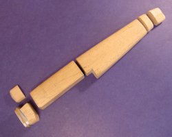
| Here's
the 1/72 fuselage with a spare bulkhead to the left by the nose. |
|
| The pictures above and to the
right are pictures of the 1/72 Wellington fuselage as it looked when
Howard gave up on it and decided to do the project in 1/48 instead.
The 1/72 plane never got past the fuselage stage. Howard was getting
a bit "buggy" from the small scale and as he got the fuselage
complete he got a hold of some more reference material that revealed a
"serious" flaw in the layout of the frame members. The
"serious" flaw had something to do with the diagonal frame
members on the top section of the plane not lining up correctly with the
diagonal side frame members on the side section to replicate the real 1/1
plane. To the average viewer of this model, this "serious"
flaw is impossible to spot and quite difficult to notice even after Howard
shows you. By this point Howard had had enough of doing this project
in 1/72 and decided to start over and do his Wellington instead in 1/48. |
| Click on
images below to see larger images. |
 |
 |
|
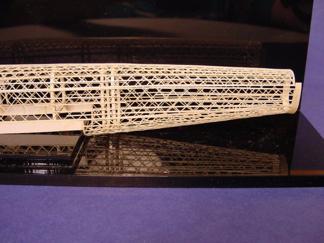
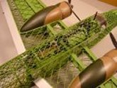
So Howard began again.
Scaling up the 1/72 Airfix fuselage to 1/48 scale Howard once again made a balsa
wood master to build his side, top and bottom sections on....one section at a
time. As he completed each section they were carefully stored away till he
had them all built and final gluing to the bulkheads was ready to begin.
How did he make the bulkheads you ask? Read on.....
| Once the sides
and top and bottom section were individually made....and stored away one
by one....it was time to cut up the balsa wood master and begin making the
bulkheads. Remember now....Howard did all these bulkheads etc in
1/72 scale first before he switched to making this model in 1/48.
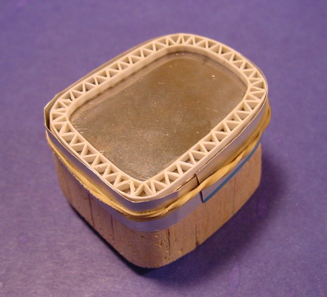
First Howard would take some very thin aluminum (like you would get in
Chinese food take out containers). He covered one end of a section of
the balsawood master with this sheet aluminum and bent it down the sides a
couple of mm. He flipped over this piece of aluminum to get a
"jig" to lay the strip styrene inside of. Howard made many
bulkheads....the one to the right is a "flawed" one that he
rejected and tossed into his spares box and made another one.
Yup...scary....it looks perfect doesn't it?....it sure looks perfect to
me. Once Howard had the "jig" for the particular bulkhead,
he would lay strip styrene around the inside of the "jig".
This first piece would be glued end to end to form the outer perimeter of
the bulkhead. Then the tiny inner pieces would be precut and glued
to the outer perimeter bulkhead piece. Finally the inner perimeter
piece would be cut and laid inside and glued end to end as well as being
glued to the rest of the bulkhead. |
| Click on
images below to see larger images. |
 |
 |
|
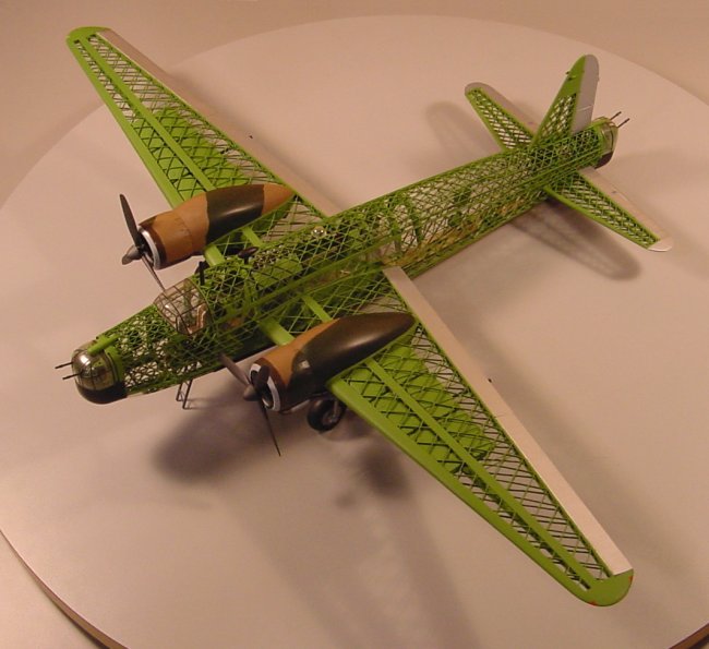
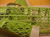
There were many bulkheads in this
model of all different sizes, all along the fuselage. You can see them in
the picture below of the finished model. One bulkhead between the cockpit
and navigator's station has a doorway cut into it.
 |
|
Here's a picture of the
finished model in 1/48
|
|
Howard needs
some reference material assistance.
Currently,
Howard is working on a 1/24
Skinless Sea Fury.
He's collected plenty of reference material, but he is stuck on 2
critical areas.
-
The
second area Howard needs info on is the hydraulic line system
throughout the entire plane. Basically Howard is looking for
any info on the placement of any and all hydraulic lines throughout
the entire plane. His 1/32 Sea Fury will have no skin, at all,
so all the details will be exposed.
Two ARC
regulars have sent in 2 articles for me to pass along to Howard.
One is the Sea Fury article from Scale Models International October 1983
and the other article is from "Scale Models" (unknown
date). Both of these articles have provided Howard with some badly
needed information and he is greatly appreciative to the 2 gentlemen
that sent these articles in.
What Howard
could really use now, is the factory manuals that show this sort of
detail....perhaps mechanics repair manuals? If someone has access
to such a book...... a few select photocopies of key pictures
would probably provide Howard with the detail he needs to complete his
Sea Fury.
Howard is an
older gent and doesn't own a computer......please send any e-mails or
info to Steve Bamford and I will
pass along the info to Howard.
Howard is
willing to pay a reasonable amount for this reference material.
Please
try to help.
I've
seen his partly built 1/32 Skinless Sea Fury....it is as cool as the
Wellington above.
Thanks!! |
| FEATURE |
FEATURE |
 |
 |
| 1/48
Scratch Built Skinless Wellington model Part 2 |
1/48
Scratch Built Skinless Wellington model Part 3
|
|
by
Howard Hill
(no Internet connection)
|
by Howard
Hill
(no Internet connection
|
|
|